Usefulness of Enhanced Stent Visualization Imaging Technique in Simple and Complex PCI Cases
Abstract: Stent underexpansion and underdeployment are associated with unfavorable outcomes including stent thrombosis, in-stent restenosis, and geographical miss. Visualization of coronary stents is increasingly difficult due to the reduction in stent strut thickness to improve deliverability. The gold standard evaluation method for stent expansion is intravascular ultrasound (IVUS), but its routine use is costly, time-consuming, and not without risk. Enhanced stent visualization is a novel fluoroscopy-based technique that improves visualization of deployed stents in the coronary arteries. We present a case series highlighting the use of this technique in percutaneous coronary intervention.
J INVASIVE CARDIOL 2014;26(10):552-557
Key words: percutaneous intervention, stent, StentBoost, enhanced stent visualization
______________________________
Coronary angiography is the primary modality to evaluate the severity of coronary artery disease and guide percutaneous intervention. Precise positioning and deployment of stents in terms of placement and expansion in relation to the flow-limiting plaque, vessel wall, other stents, and side branches are very important for the success of percutaneous coronary intervention (PCI) and longer-term outcomes.1
Continuous stent design advances have led to thinner stent struts, which allow better stent deliverability, but limit visibility with fluoroscopy imaging. Enhanced stent visualization (ESV)2,3 is an advanced fluoroscopic imaging alternative to intravascular ultrasound (IVUS) for assessing stent placement and expansion. This technique provides enhanced stent frame visualization and eliminates motion artifacts without adding procedural time or cost to conventional angiography. The majority of the current literature is restricted to case reports describing specific devices or complications.4 Others have focused on comparisons between ESV and IVUS.5 This paper highlights multiple cases to elucidate how this technology can be incorporated into daily clinical practice to support PCI in a wide variety of clinical scenarios.
Methods
ESV is acquired using cine acquisition, usually without contrast injection. It can be acquired before stent deployment to check stent position, or after deployment. The ESV system uses markers, for example those of the stent-deployment balloon, to correct for breathing and cardiac motion. It does this by registering, matching, and averaging images from each cine frame in relation to the two markers. This results in an enhanced image of the stent with improved resolution and a superior signal-to-noise ratio. Optionally, the enhanced stent image can be automatically superimposed on a contrast-filled coronary artery image and allows for the easier assessment of stent deformation, expansion, overlap with other stents, and apposition. A balloon catheter with radiopaque markers must remain in the region of interest to allow the automatic registration and processing of all frames within the acquired sequence.
Some of the technical aspects that must be taken into account while acquiring stent boost images are that fluoroscopically bright objects, such as surgical clips, pacemaker and sternotomy wires, which decrease image quality, should be excluded from the region of interest. While acquiring images and measurements, meticulous attention should be paid to avoid foreshortening.
Case Series
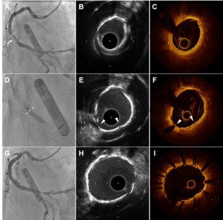
Case 1. Obese patient with small-vessel disease (Figure 1). A 43-year-old, obese (body mass index [BMI], 35), newly diagnosed type-2 diabetic woman presented with intractable angina. Her coronary angiogram showed subtotal occlusion of  one of the small divisions of diagonal branch of the left anterior descending (LAD) artery. This small branch was stented using a 2.25 x 14 mm drug-eluting stent (DES) with excellent result. ESV proved very useful in clearly visualizing the stent in this obese patient with small-vessel disease, which may not have been possible with fluoroscopy views alone.
Case 2. Case of underdeployment and postdilatation (Figure 2). A 69-year-old diabetic woman presented with unstable angina. Her coronary angiogram showed severe mid-right coronary artery (RCA) stenosis. This lesion was stented using a 3.5 x 18 mm DES. The stent was postdilated to high pressures. Postprocedure ESV demonstrated inadequate stent strut expansion toward the proximal edge of the stent, which was further dilated using 4.0 mm non-compliant balloon. The ESV images also demonstrated postdilatation change in stent diameter.
Case 3. Long lesion and multiple overlapping stents (Figure 3). An 81-year-old male ex-smoker with a prior history of PCI to the ramus intermediate presented with non-ST segment elevation myocardial infarction (NSTEMI). His coronary  angiogram showed 3 severe calcified tandem lesions in the mid and distal LAD. PCI to the LAD lesions was performed using DESs. The ESV technique proved very useful in identifying stent edges for appropriate stent overlapping.
Case 4. Calcified lesion (Figure 4). A 70-year-old female presented with NSTEMI. Her coronary angiogram showed heavily calcified severe ostial LAD stenosis. There was also severe calcified lesion in the mid-LAD, left circumflex (LCX) artery, ramus intermediate, and RCA. Surgical revascularization was declined due to comorbidities. The patient underwent PCI with DES to the ostial LAD and distal left main coronary artery (LMCA). The ESV images demonstrated stent underexpansion with a waist in the region of heavy calcification. The stent was postdilated. ESV proved very useful in distinguishing stent margins from the calcification, thereby reducing the risk of dissection in a calcified vessel while still allowing high-pressure postdilatation.
Case 5. Prior bifurcation stent (Figure 5). A 55-year-old male with prior PCI to his LAD at another hospital presented with lateral ST-segment elevation myocardial infarction (STEMI). No details of the prior PCI procedure were available. An urgent  angiogram showed severe stenosis in the mid-LAD. Stent boost images prior to PCI visualized clearly the prior bifurcation stent in the mid-LAD just distal to the lesion. PCI was performed with a DES, with the distal edge of the new stent overlapping with the previous one by about 2 mm.
Case 6. Bifurcation lesion (Figure 6). A 70-year-old male presented with anterior STEMI. A coronary angiogram showed severe thrombotic proximal LAD occlusion involving the LAD/first diagonal (D1) bifurcation. The LAD was stented with a 3.0 x 18 mm DES and a 2.5 x 14 mm DES was deployed to the D1 branch. The LAD/D1 balloons were kissed with good result.
Case 7. Bifurcation tapping technique (Figure 7). A 45-year-old male presented with NSTEMI. His coronary angiogram showed a complex lesion in the mid-LAD involving the diagonal branch. A DES was deployed to the diagonal artery and then  tapped with minimal protrusion back with a 2.5 mm balloon and a second DES was then deployed to the LAD. The diagonal and LAD were postdilated with kissing balloons.
Case 8. Ostial RCA stenosis (Figure 8). A 70-year-old male with prior history of hypertension, dyslipidemia, and family history of coronary artery disease presented with exertion angina. His nuclear scan showed reversible ischemia in the RCA. Angiography demonstrated severe ostial RCA stenosis. The lesion was direct stented with a 3.5 x 15 mm DES. ESV showed stent underdeployment proximally, which was postdilated with a 3.75 non-compliant balloon to 24 atm with excellent outcome.
Case 9. In-stent restenosis (Figure 9). A 56-year-old male with a history of diabetes and PCI to his RCA with DES implantation presented with angina. A scintigraphic study then revealed reversible ischemia in the RCA territory. His coronary angiogram showed critical in-stent restenosis of his distal RCA stent. Percutaneous intervention to the lesion was performed using a 3.0 x 20 mm drug-eluting balloon (DEB). ESV was useful in accurate positioning of the DEB.
Case 10. Left main/left anterior descending coronary artery in-stent restenosis (Figure 10). A 64-year-old male presented with chest pain and ventricular tachycardia. His prior coronary intervention details were not known. Coronary angiogram revealed severe in-stent restenosis of his left main/proximal LAD stent, with diffuse disease in the circumflex artery. The ESV images acquired prior to initial balloon inflation demonstrated passage of the balloon through the stent struts.
Discussion
Stents are often suboptimally imaged in conventional two-dimensional (2D) angiography, potentially limiting optimal procedural outcomes.6 It is difficult to determine the vessel and stent dimensions from a 2D image. In addition, high temporal  resolution is needed to visualize a moving structure. The major limitation of qualitative and quantitative coronary angiography is decreased sensitivity in detecting stent underexpansion,7 which is a predictor of both stent thrombosis and in-stent restenosis. ESV is superior to conventional angiography alone and quantitative measurements have shown strong correlation with IVUS.8
The current gold standard for the detection of stent underexpansion is IVUS.9-12 IVUS has been used to optimize PCI outcomes via sizing vessels and verifying the optimal expansion of stents. Improved procedural outcomes, such as increased luminal diameter and reduced restenosis rates have been documented when using IVUS with PCI.10,13 However, IVUS cannot directly guide stent placement and is, in most countries, limited by cost, procedural time, professional and technical expertise, and the need for additional training of staff in catheterization laboratories. Furthermore, there is a small risk of increased mechanical complications, particularly coronary spasm.14 Recently, optical coherence tomography (OCT) has also been used to assess vessel size and stent expansion, but the technique has similar limitations to IVUS.15 In both retrospective and prospective studies, post-stent fractional flow reserve (FFR) measurements have been shown to be a strong independent predictor of adverse outcomes.16,17 However, its routine use for stent deployment is not practical due to the additional procedure, extra cost, and time involved. FFR cannot detect stent underexpansion. 
ESV is very useful for identifying stent underdeployment and malapposition, and for positioning a postdilatation balloon. The areas of stent underexpansion are easily identifiable and can be postdilated. Use of ESV technique to demonstrate adequate stent expansion in routine PCI has shown to be useful. Use of ESV has been shown to improve PCI outcomes. In a retrospective observational study of 870 patients, ESV-guided PCI was reported to be associated with better mid-term angiographic and clinical outcomes.18 Stent visualization can also help identify stent fractures and cases have been reported where ESV demonstrated stent fracture despite lack of IVUS evidence.19
Some of the advantages of ESV are: little additional procedural time; better image resolution than cineangiography; no risk of mechanical complication; and better correlation with IVUS compared to quantitative coronary angiography. Currently available ESV systems include StentBoost (Philips Medical Systems), StentViz (GE Healthcare), IC Stent (Siemens Healthcare), and StentOptimizer (Paieon). While most of the features between various available systems are comparable, it has been suggested that the non-linear registration process utilized in the StentViz algorithm may allow more accurate measurement of stent dimensions.20 StentBoost was used in the above-mentioned cases.
We found ESV particularly useful in the following clinical situations:
Obese patients. Obesity decreases fluoroscopic resolution, and it’s difficult to identify areas of inadequate stent expansion. ESV improves the ability to assess stent underexpansion in obese patients.
Long lesions. Implantation of two or more adjacent sequential stents is frequently required during PCI, eg, with different proximal and distal reference vessel diameters or when an edge dissection occurs from a previously implanted stent. While deploying an overlapping or sequential stent, ESV can demonstrate the exact location of previously deployed stents and the degree of overlap and can facilitate proper stent positioning in relation to prior stents. Any gaps between the stents can be corrected during the procedure.
In-stent restenosis and stent-in-stent implantation. In previously stented vessels with in-stent restenosis, ESV can help with proper balloon and stent position in relation to previous stent(s).
Bifurcation lesions. ESV allows the accurate assessment of the deformation and the expansion of a stent during sequential inflations in the main artery and the ostium of the side branch and during the simultaneous inflation of the both branches (kissing-balloon technique), thus creating an almost “virtual” bench test.21
Alternative to invasive imaging. In most cases, ESV provides a cost-effective and more time-efficient alternative to IVUS or OCT for assessing adequate stent deployment. In our clinical practice, most cases do not need IVUS or OCT to assess stent expansion as ESV provides the required information. IVUS is cumbersome in cases of bifurcation lesions, where advancing the IVUS catheter across both vessel arms is required. ESV provides an efficient means of evaluating stent expansion in bifurcation lesions. A few studies have compared ESV with IVUS and quantitative coronary angiography; they suggested accurate estimation of stent expansion with ESV, and better correlation with IVUS than QCA.2,22-24 We suggest that ESV  technology be used routinely to assess and guide stent deployment, and the operator could proceed to more invasive technologies like IVUS or optical coherence tomography in cases of ongoing uncertainty. Future comparative studies between this technology and IVUS will be necessary to investigate impact on outcomes, particularly in relation to newer-generation DESs with thinner struts, as well as bioresorbable vascular scaffold systems.
Conclusion
ESV is a newer imaging modality that provides enhanced stent visualization by eliminating motion artifact. It is a simple and cost-effective stent visualization technique that facilitates non-invasive assessment of stent positioning, stent expansion, and stent-vessel interactions. It does not increase procedure or fluoroscopy time and is complementary to IVUS and in some cases obviates its need.
References
- Costa MA, Angiolillo DJ, Tannenbaum M, et al; STLLR Investigators. Impact of stent deployment procedural factors on long-term effectiveness and safety of sirolimus-eluting stents (final results of the multicenter prospective STLLR trial). Am J Cardiol. 2008;101(12):1704-1711.
- Mishell JM, Vakharia KT, Ports TA, Yeghiazarians Y, Michaels AD. Determination of adequate coronary stent expansion using StentBoost, a novel fluoroscopic image processing technique. Catheter Cardiovasc Interv. 2007;69(1):84-93.
- Cura F, Albertal M, Candiello A, et al. StentBoost visualization for the evaluation of coronary stent expansion during percutaneous coronary interventions. Cardiol Ther. 2013;2(2):171-180.
- Shinde RS, Hardas S, Grant PK, Makhale CN, Shinde SN, Durairaj M. Stent fracture detected with a novel fluoroscopic stent visualization technique — StentBoost. Can J Cardiol. 2009;25(8):487.
- Tanaka N, Pijls NH, Koolen JJ, et al. Assessment of optimum stent deployment by stent boost imaging: comparison with intravascular ultrasound. Heart Vessels. 2013;28(1):1-6.
- Cheneau E, Leborgne L, Mintz GS, et al. Predictors of subacute stent thrombosis: results of a systematic intravascular ultrasound study. Circulation. 2003;108(1):43-47.
- Blasini R, Neumann FJ, Schmitt C, Bökenkamp J, Schömig A. Comparison of angiography and intravascular ultrasound for the assessment of lumen size after coronary stent placement: impact of dilation pressures. Cathet Cardiovasc Diagn. 1997;42(2):113-119.
- Fujii K, Mintz GS, Kobayashi Y, et al. Contribution of stent underexpansion to recurrence after sirolimus-eluting stent implantation for in-stent restenosis. Circulation. 2004;109(9):1085-1088. Epub 2004 Mar 1.
- de Feyter PJ, Kay P, Disco C, Serruys PW. Reference chart derived from post-stent-implantation intravascular ultrasound predictors of 6-month expected restenosis on quantitative coronary angiography. Circulation. 1999;100(17):1777-1783.
- de Jaegere P, Mudra H, Figulla H, et al. Intravascular ultrasound-guided optimized stent deployment. Immediate and 6 months clinical and angiographic results from the Multicenter Ultrasound Stenting in Coronaries Study (MUSIC Study). Eur Heart J. 1998;19(8):1214-1223.
- Hoffmann R, Mintz GS, Mehran R, et al. Intravascular ultrasound predictors of angiographic restenosis in lesions treated with Palmaz-Schatz stents. J Am Coll Cardiol. 1998;31(1):43-49.
- Mintz GS, Nissen SE, Anderson WD, et al. American College of Cardiology Clinical Expert Consensus Document on Standards for Acquisition, Measurement and Reporting of Intravascular Ultrasound Studies (IVUS). A report of the American College of Cardiology Task Force on Clinical Expert Consensus Documents. J Am Coll Cardiol. 2001;37(5):1478-1492.
- Mudra H, di Mario C, de Jaegere P, et al; OPTICUS (OPTimization with ICUS to reduce stent restenosis) Study Investigators. Randomized comparison of coronary stent implantation under ultrasound or angiographic guidance to reduce stent restenosis (OPTICUS Study). Circulation. 2001;104(12):1343-1349.
- Hausmann D, Erbel R, Alibelli-Chemarin MJ, et al. The safety of intracoronary ultrasound. A multicenter survey of 2207 examinations. Circulation. 1995;91(3):623-630.
- Mehanna EA, Attizzani GF, Kyono H, Hake M, Bezerra HG. Assessment of coronary stent by optical coherence tomography, methodology and definitions. Int J Cardiovasc Imaging. 2011;27(2):259-269. Epub 2011 Feb 19.
- Pijls NH, Klauss V, Siebert U, et al. Coronary pressure measurement after stenting predicts adverse events at follow-up: a multicenter registry. Circulation. 2002;105(25):2950-2954.
- Nam CW, Hur SH, Cho YK, et al. Relation of fractional flow reserve after drug-eluting stent implantation to one-year outcomes. Am J Cardiol. 2011;107(12):1763-1767.
- Oh DJ, Choi CU, Kim S, et al. Effect of StentBoost imaging guided percutaneous coronary intervention on mid-term angiographic and clinical outcomes. Int J Cardiol. 2013;168(2):1479-1484. Epub 2013 Jan 16.
- Kim MS, Eng MH, Hudson PA, et al. Coronary stent fracture: clinical use of image enhancement. JACC Cardiovasc Imaging. 2010;3(4):446-447.
- Bismuth V, Vaillant R, Funck F, Guillard N, Najman L. A comprehensive study of stent visualization enhancement in x-ray images by image processing means. Med Image Anal. 2011;15(4):565-576.
- Agostoni P, Verheye S, Vermeersch P, Cornelis K, Van Langenhove G. “Virtual” in-vivo bench test for bifurcation stenting with “StentBoost.” Int J Cardiol. 2009;133(2):67-69.
- Sanidas EA, Maehara A, Barkama R, et al. Enhanced stent imaging improves the diagnosis of stent underexpansion and optimizes stent deployment. Catheter Cardiovasc Interv. 2013;81(3):438-445. Epub 2012 May 2.
- Davies AG, Conway D, Reid S, Cowen AR, Sivananthan M. Assessment of coronary stent deployment using computer enhanced x-ray images-validation against intravascular ultrasound and best practice recommendations. Catheter Cardiovasc Interv. 2013;81(3):419-427.
- Yang FF, Zhang LW, Huang DS, et al. A novel angiographic technique, StentBoost, in comparison with intravascular ultrasound to assess stent expansion. Chin Med J (Engl). 2011;124(6):939-942.
_________________________________
From the 1Department of Cardiology, Northern Hospital, Melbourne, Australia; 2Department of Medicine, University of Melbourne, Melbourne, Australia; 3St Vincent’s Hospital, Melbourne; and 4Philips Medical Systems Nederland BV, Best, The Netherlands.
Disclosure: The authors have completed and returned the ICMJE Form for Disclosure of Potential Conflicts of Interest. Dr den Hartog is an employee of Philips Medical Systems. The remaining authors report no disclosures.
Manuscript submitted November 25, 2013, provisional acceptance given January 13, 2014, final version accepted February 3, 2014.
Address for correspondence: Dr Muhammad Asrar ul Haq, Department of Cardiology, The Northern Hospital, 185 Cooper Street, Epping, VIC 3076. Email: muhammad.asrar@unimelb.edu.au


