


How Partial Skull Defect Affects Vulnerability of the Skull in Traumatic Situations: A Biomechanical Study
Abstract
Background. Part of the skull can be lost due to neurosurgical diseases or trauma. Skulls with partial defects can develop different fracture patterns from those of intact skulls. This study aims to clarify the differences.
Methods. A 3-dimensional skull model was produced by referring to the computer-tomography data of a 23-year-old intact male volunteer. We defined the model as Intact Model. Another model was produced by removing part of the frontal bone, which was defined as Defect Model. Dynamic simulations of impacts were performed varying the site and direction of impact. Fracture patterns caused by the impacts were calculated using dynamic analysis software (LS-DYNA; Livermore Software Technology Corp.) and were compared between the intact model and defect model.
Results. When Defect Model was impacted, fracture involved wider areas than when Intact Model was impacted. This finding was observed not only when Defect Model was impacted on its defect side but also when it was impacted on its intact side.
Conclusions. When a skull carrying a defect on one side is impacted, serious fracture occurs even when the non-defect side is impacted, meaning that a skull with a defect is vulnerable to impacts on the non-defect side. This finding should be taken into consideration in deciding indications of skull defect reconstruction.
Introduction
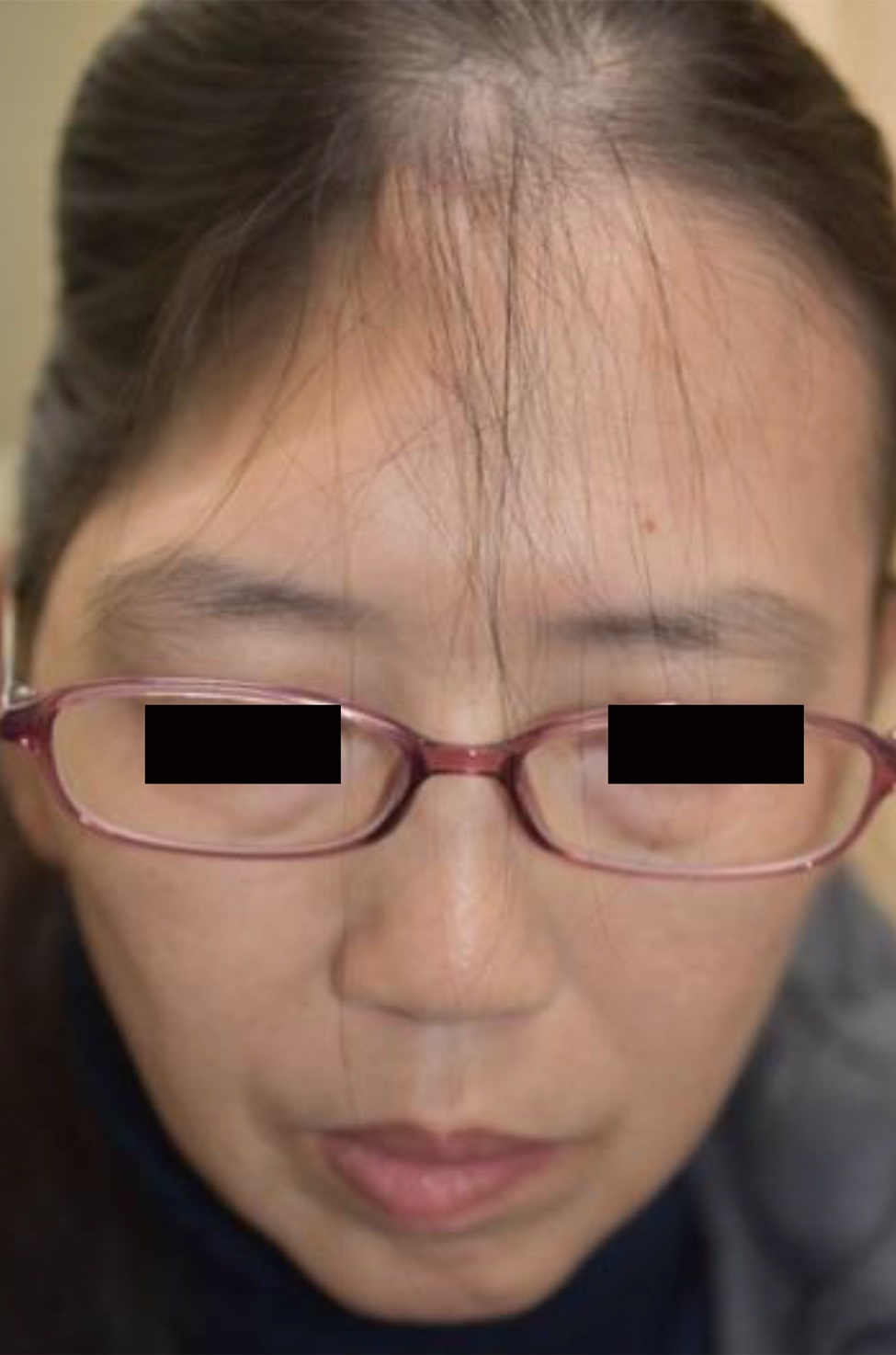
Partial cranial defects can occur when part of the skull is damaged in trauma situations.1,2 To decompress increased intracranial pressure due to brain tumors or intracranial hemorrhage,3,4 bone pieces are temporarily removed. Though the removed pieces are usually replaced in their original positions, the pieces sometimes develop infection and are therefore discarded,5 causing partial defect of the skull (Figure 1). Partial defects of skulls can be restored with artificial bone,6-8 titanium plates,9-11 and autogenous tissues.12,13
However, patients with partial defects do not necessarily wish to have the defects restored; some patients have received multiple surgeries and are often frustrated by more surgery. In deciding whether to perform skull reconstruction surgery, merits and demerits of the reconstruction surgery must be considered. One possible demerit is a potential increase in the vulnerability of the skull in trauma situations. Intuitively, it seems possible that when impacted, a skull that has a defect will be damaged more seriously than an intact skull. However, no evidence has been provided to this stipulation, so far. The present study performs dynamic simulations by using 3-dimensional computer models to investigate how the presence of a partial skull defect affects the biomechanical vulnerability of the skull.
Methods and Materials
This study was conducted under the approval of the research ethics committee of Kagawa University (Approval Number: H29-170).
Production of 3-dimensional computer models of the skull
Computed tomography (CT) data of a 23-year-old male volunteer, who received CT examination to screen for brain injury after striking his head during a traffic accident, were used to produce 3-dimensional computer skull models. The examination revealed damage to neither his skull nor his brain, and his skull showed no congenital deformity. The CT data were transferred to preprocessor software (Scan IP; Simpleware Ltd.) as DICOM (Digital Imaging and Communications in Medicine) files and then transformed to STL (Standard Triangulated Language) files, forming a 3-dimensional simulation model of the skull. This model was defined as Intact Model. Simulating decompression craniectomy, part of the bone was removed from the left anterior-lateral region of Intact Model by using 3-dimensional graphic software (Geomagic Freeform; 3D SYSTEMS).
The model with the defect was defined as Defect Model. By using the preprocessor software (Scan IP) again, Intact Model and Defect Model were transformed to finite element models consisting of 2,230,000 and 1,820,000 tetrahedrally shaped 10-node elements, respectively. Specific density of the skull bone was calculated by translating Housefield gray scale14; Young’s modulus was calculated based on the equation of Kopperdahl {E = -34.7 + 3230 QCT}, where E and QCT mean Young’s modulus (in MPa) and CT density, respectively.15 The calculated material properties were assigned to the finite element models.
Dynamic Simulation of Impact Application
Modeling of Striking Tool
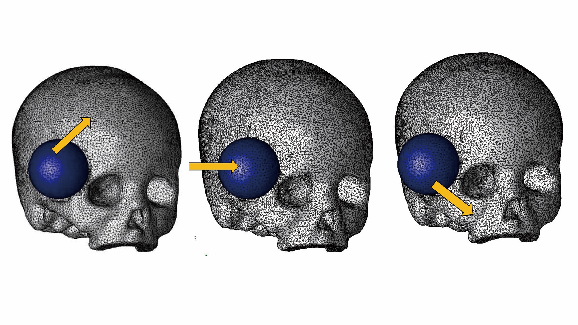
Simulating a lead ball with a diameter of 25 mm, a sphere-shaped finite element model was produced. The specific gravity and Young’s modulus of lead were assigned to the ball.
Conditions of Impact Application
The junction between the frontal bone and the zygoma was defined as anterior-lateral (AL) point. The horizontal plane crossing the AL point, the sagittal plane crossing the tragus, and the coronal plane crossing the tragus intersect at a point. That point was defined as temporal-lateral (TL) point.
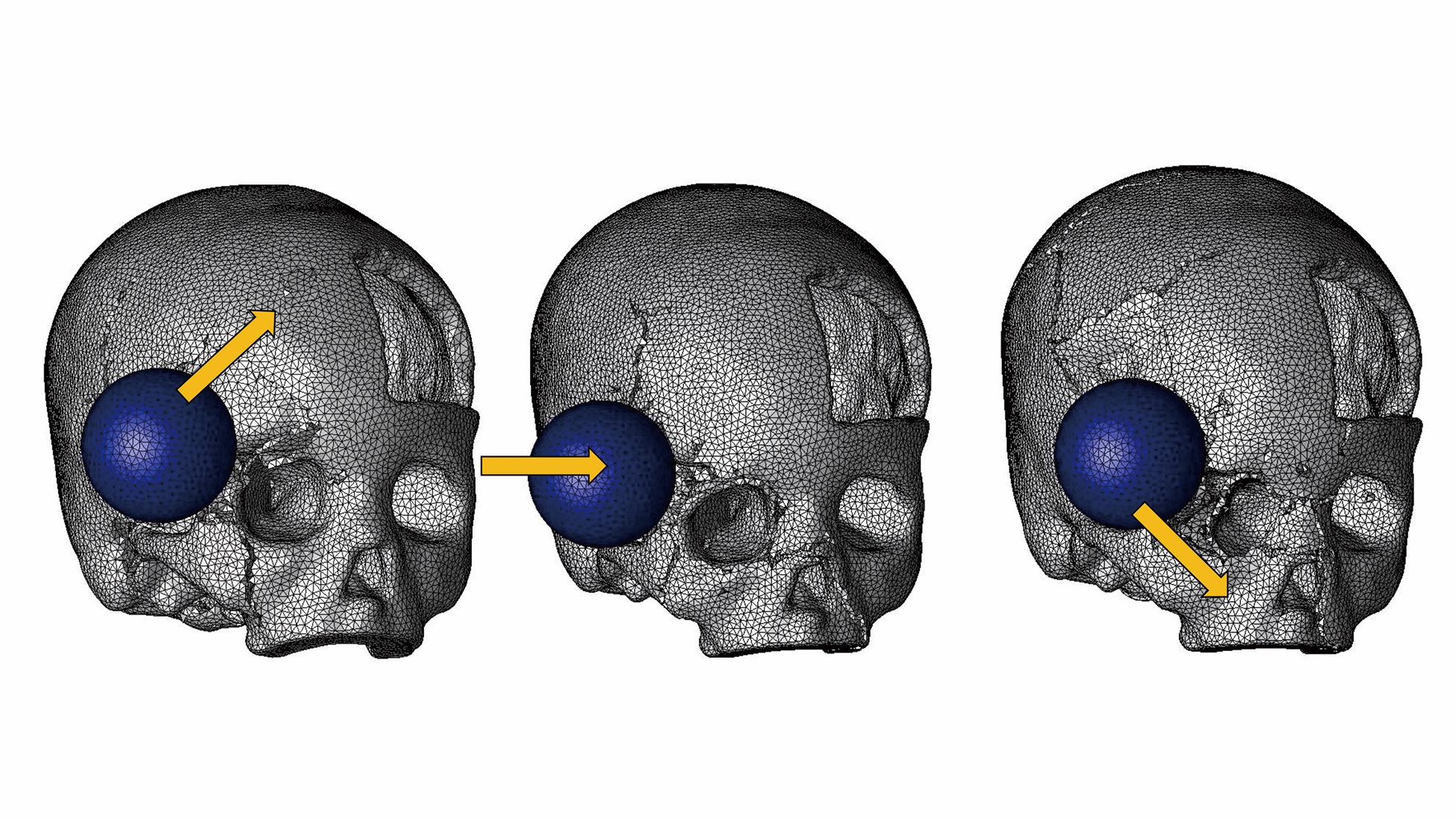
Intact Model and Defect Model were impacted with the ball model in the following conditions (Figure 2):
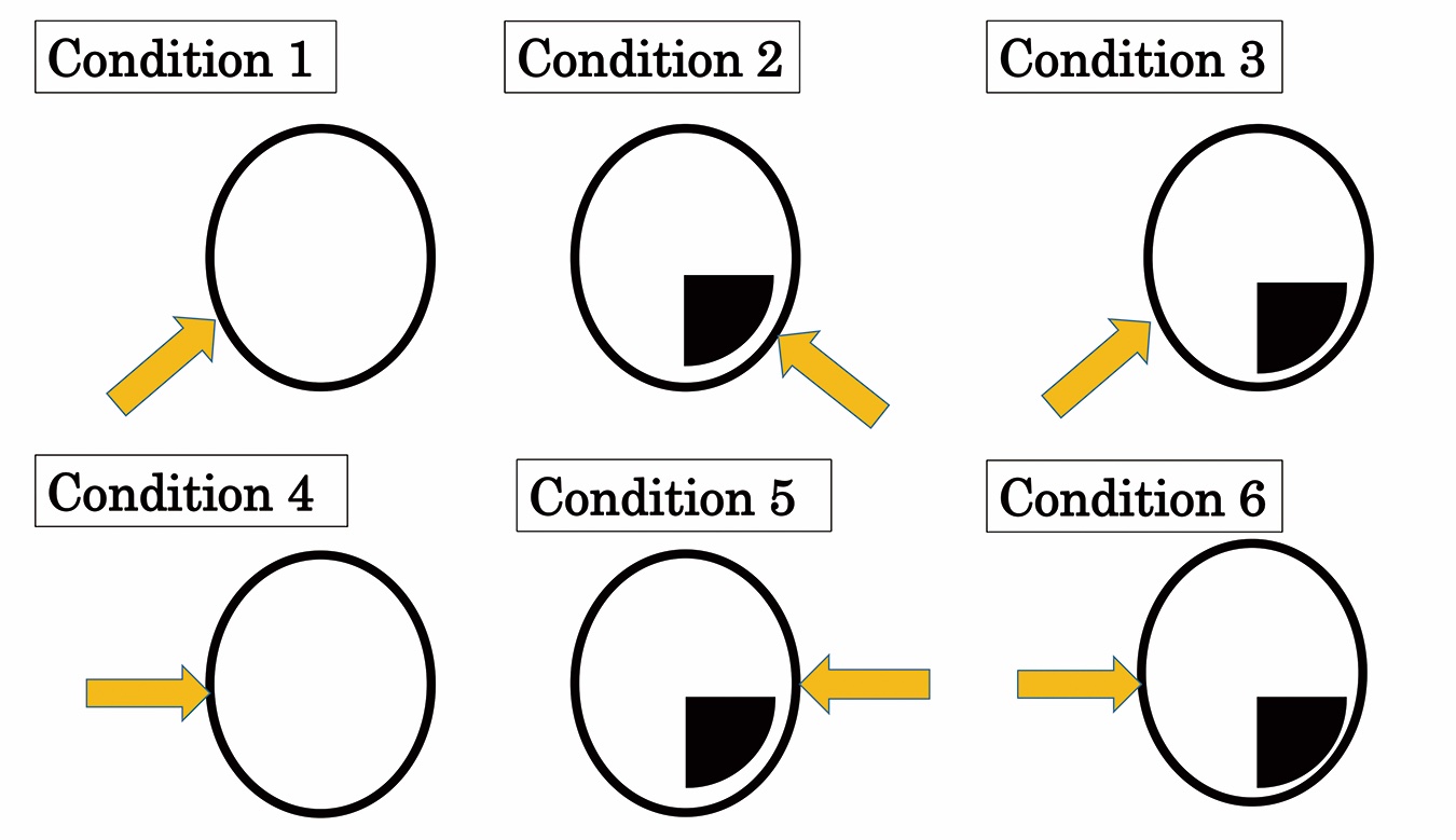
Condition 1: Intact Model impacted at right AL point
Condition 2: Defect Model impacted at left AL point
Condition 3: Defect Model impacted at right AL point
Condition 4: Intact Model impacted at right TL point
Condition 5: Defect Model impacted at left TL point
Condition 6: Defect Model impacted at right TL point
Velocity and Direction of Impact
The lead ball model was initially placed 5 mm away from the skull models. Then the ball model was launched at a velocity of 10 m/s. For each of the 6 impact application patterns, the ball was launched varying the direction in 3 ways: at 30° of elevation (meaning upward), horizontally (meaning parallel to Frankfort Plane), and at 30° of depression (meaning downward).
Calculation
Dynamic calculation was performed under the above-stated conditions with LS-DYNA, and fracture patterns resulting from the impact were calculated. Transient analysis was used in the calculation, wherein an element disappears when the strain occurring on it exceeds its breakdown threshold. The yield threshold of the bone was assumed to be 150 MPa.16
Evaluation
After the conditions of fracture caused by impacts were calculated, the positions and degrees of fracture were evaluated.
Results
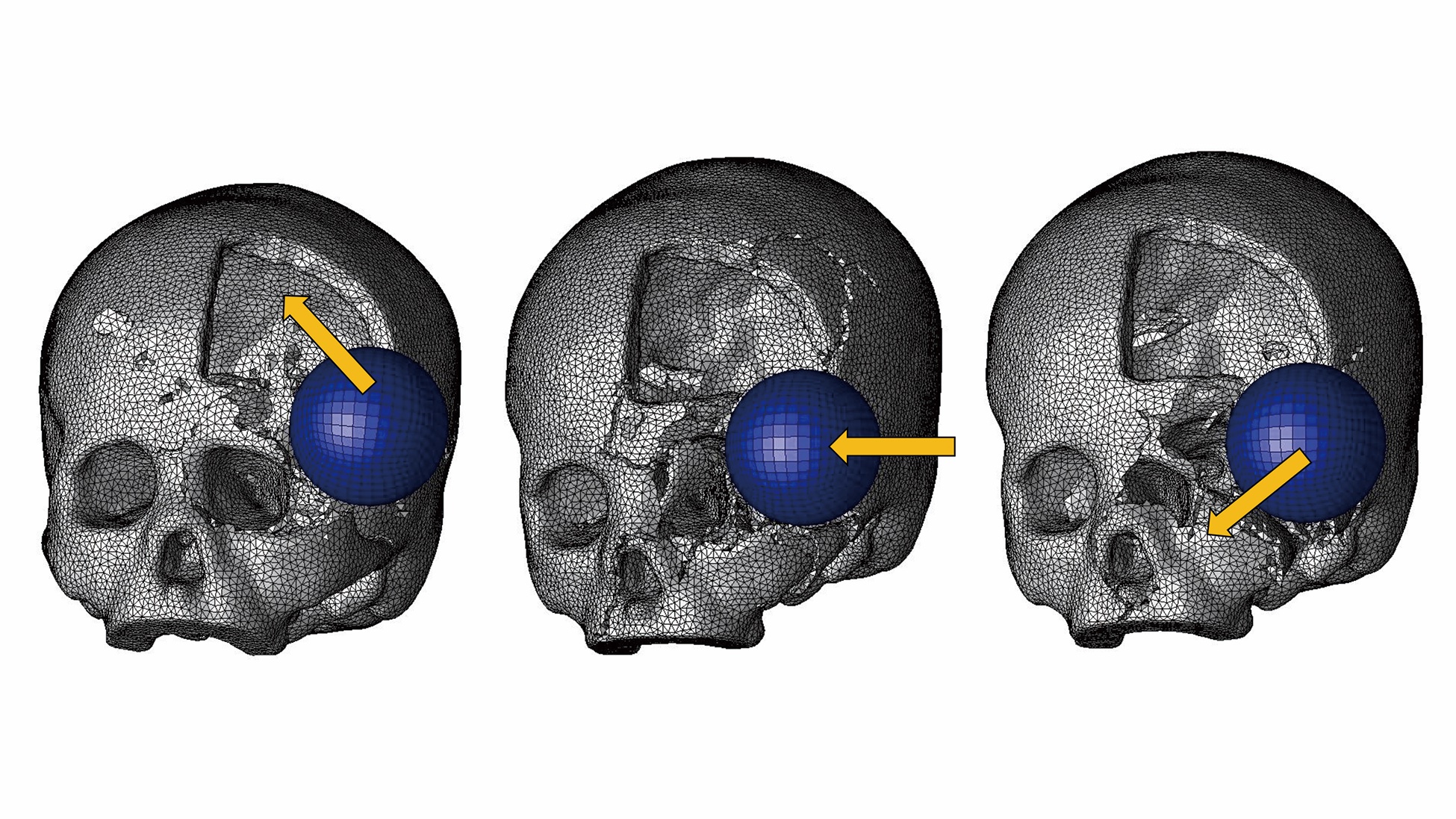
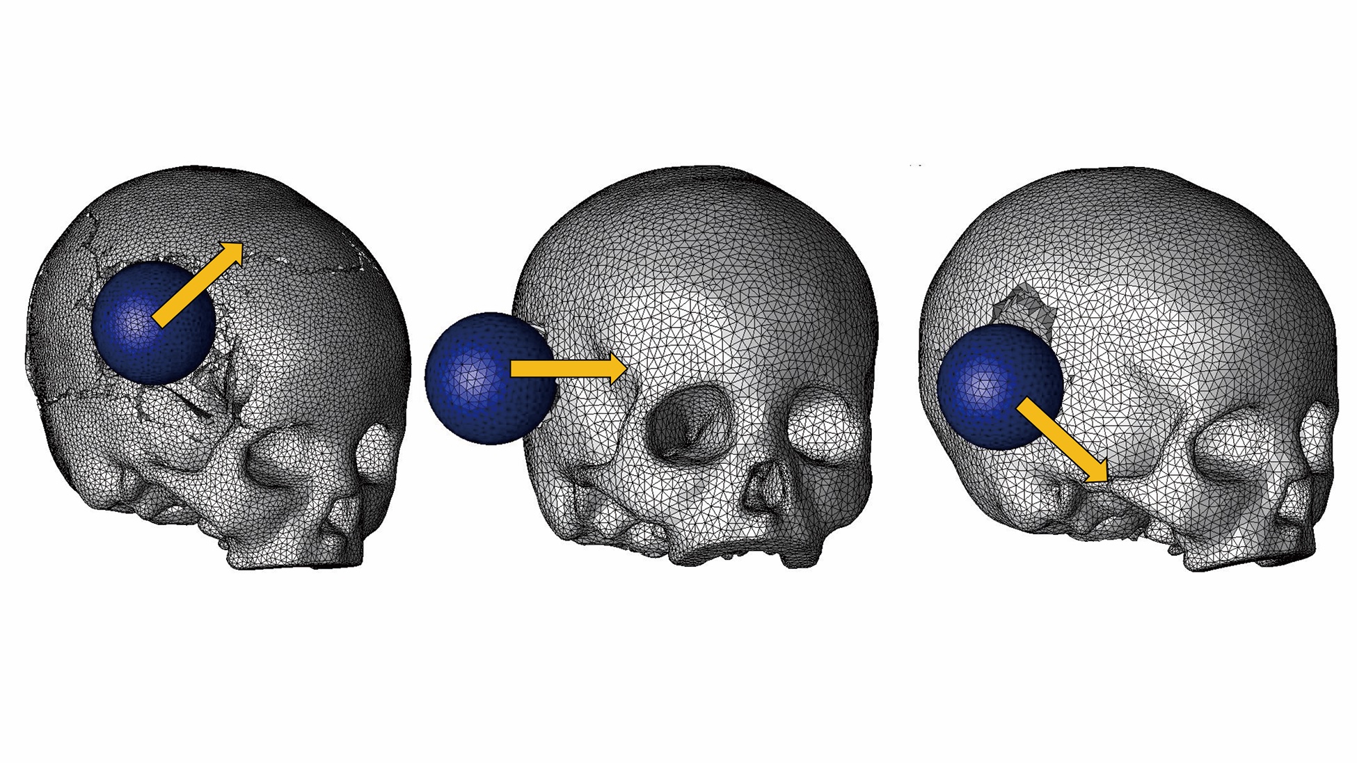
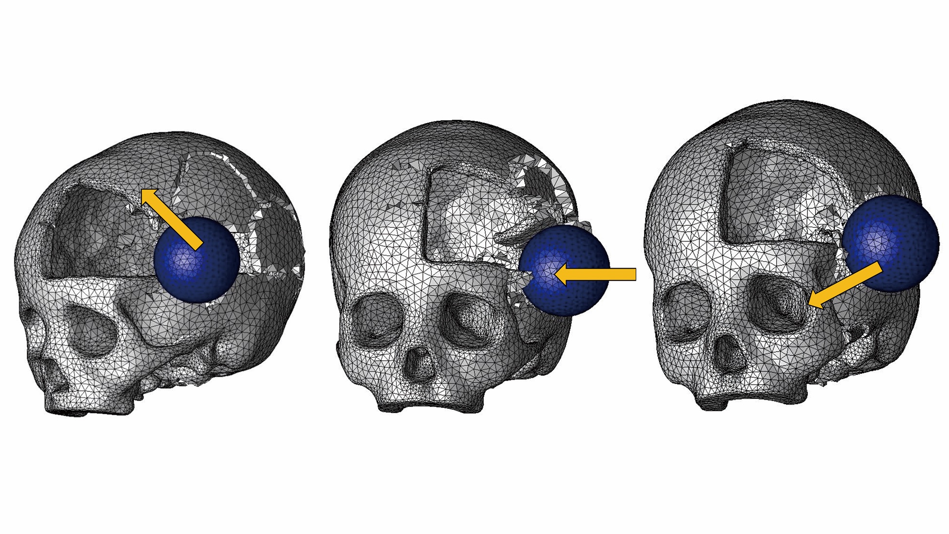
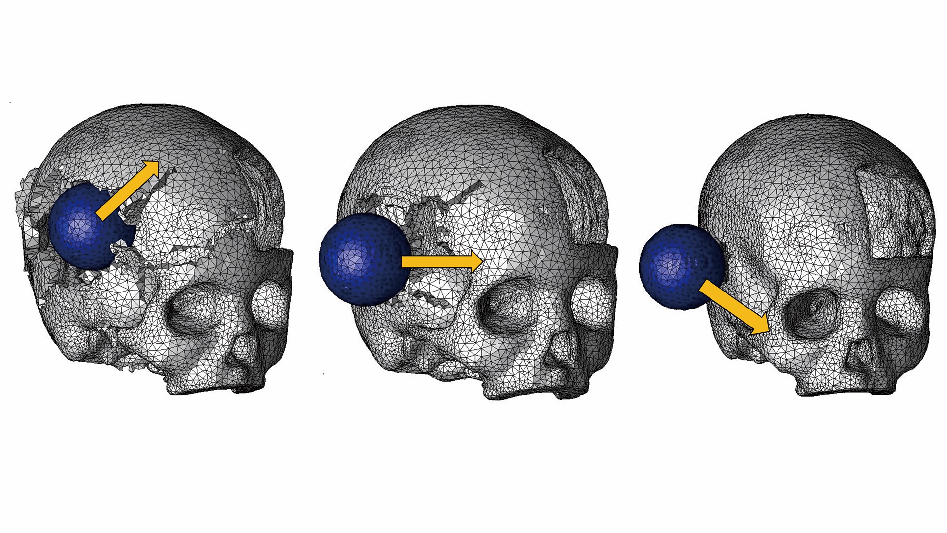
Fractures occurring in the 6 conditions are shown in Figures 3-8. The findings are summarized as follows.
When the defect side of a skull with a defect is impacted, serious fractures occur.
In Condition 1, fracture localizes near the impact area (Figure 3). In Condition 2, in contrast, fracture extends to wide areas beyond the impacted site (Figure 4). Similarly, in Condition 5 (Figure 7), fracture extends to a much wider area than in Condition 4 (Figure 6).
These findings indicate that when a skull with a defect is impacted on its defect side, serious fractures occur.
When the non-defect side of a skull is impacted, more serious fracture occurs than when an intact skull is impacted.
In Condition 3 (Figure 5), fracture occurs across wider areas than in Condition 1 (Figure 3). Similarly in Condition 6 (Figure 8), fracture involves wider areas than in Condition 4 (Figure 6). These findings indicate that when a skull with a defect is impacted, even when the non-defect side is impacted, more serious fracture occurs than when a normal skull is impacted.
Discussion
Partial defects of the skull can be caused by injury or by decompression of intracranial pressure for the treatment of intracranial hemorrhage or brain tumors. We raised the clinical question of whether or not the presence of partial skull defects increases the vulnerability of the skull in trauma situations. This question is important from a clinical viewpoint because patients who have skull defects may fall and hit their heads while walking or be involved in traffic accidents due to impaired motor functions. In addition to this clinical interest, we conducted the present study to clarify the relationship between partial skull defect and the vulnerability of the skull.
Methodologically, the simplest way to evaluate the vulnerability of skulls is to strike actual skulls. However, accurate replication of experimental conditions is difficult in this method. Because of the structural complexity of the skull, subtle differences in striking sites and directions can greatly affect subsequent fracture patterns. Furthermore, use of skulls for experimental purposes raises controversy from ethical standpoints. Therefore, we conducted computer simulation rather than using actual skulls in this study.
Computer simulation with the finite element method is an established method in craniofacial research and is used to clarify the occurrence mechanisms of orbital floor fractures17 and frontal bone fractures18,19 and in the evaluation of operational risks in Le Fort 3 osteotomy.20 Computer simulation allows us to apply impact at specific sites of the skull with specific directions. Moreover, computer simulation on virtual skulls is not ethically controversial. Because of these advantages, computer simulation was used in the present study.
Limitations
In the present study, models simulating merely the bone part of the head were produced. However, the actual head contains soft tissues such as the scalp, fat, and muscles. These soft tissues can function as shock absorbers when the head is impacted. Accordingly, fractures occurring on actual heads can be less serious than those on bare skulls. It is expected that the general findings with skull models―that more serious fractures can occur in defective skulls than in intact skulls—also hold true with actual heads. However, inclusion of soft tissues in the simulation models would make the results more persuasive. Models for future studies will attempt to incorporate these considerations.
The findings of the present study are summarized as 2 propositions. First, when a defective skull is impacted on the side of the defect, serious fractures occur. Second, even when the non-defect side of a defective skull is impacted, fracture becomes more serious than when the equivalent site of an intact skull is impacted.
The first finding confirms what people would intuitively surmise. When the head of a patient who has a defect is impacted on the side of the defect, a wide area of the skull is destroyed, potentially accompanied by serious damage of the brain. Patients should take care to protect the defective sides in their daily lives.
The second finding is important for patients making decisions on whether or not to receive skull reconstruction surgery. For patients who have life-threatening diseases such as malignant tumors, the decision of whether or not to receive the surgical treatment is not difficult because the rejection of treatment results in death.
When the defect of the skull remains unrepaired, the patient can occasionally develop headache or depression. These symptoms, called sinking skin flap syndrome or trephined syndrome, are caused by unstable intracranial pressure due to a lack of brain protection. Reconstruction is effective to prevent this complication, so it is preferable that the skull be reconstructed.21,22 Besides the prevention of skin flap syndrome, the skull should be repaired to avoid serious brain injury. The brain under the skull defect can be seriously damaged if the defective part is impacted in accidents or other trauma situations. Hence, in cases where the defects were not reconstructed in emergency care, such as warfare-related skull injury, skulls are often reconstructed in secondary treatments.23,24
Despite the importance of secondary cranial reconstruction, patients with skull defects often remain undecided whether or not to receive skull reconstruction surgery because rejection of the surgery is not fatal. To support the decision-making process of these patients, detailed information should be provided regarding the advantages and disadvantages of skull reconstruction. Although accurate understanding of the vulnerability of the defective skull should be a part of such information, little such information has been available.
The lack of objective information can mislead patients. For instance, some patients might think, “I have a defect in my skull. I know the brain might be seriously damaged if the skull around the defect is struck. However, if only I take care not to expose the defective side, I’ll be safe,” and refuse to receive skull reconstruction. However, the second finding shows that even if the intact side of the head is struck, serious fractures can occur. Proof of this phenomenon might encourage patients to undergo restoration surgery of the skull.
Patients with partial skull defects usually protect their heads with special helmets. The second finding provides a guiding concept for designing such protection. Intuitively, it appears that mere coverage of the area overlying the skull defect is enough to protect the brain. However, the second finding demonstrates that impact application on the non-defect side of the skull can cause serious brain damage. Therefore, protection should be designed so that it protects not only the defective side of the skull but also the intact side. Thus, taking the second finding into consideration in designing head protection can avoid the occurrence of serious brain damage.
Conclusions
This study demonstrates the influence of partial skull defects on the mechanical vulnerability of the skull. Three-dimensional computer models of the skull were produced, and dynamic impacts were applied to them. Observation of subsequent fracture patterns was performed. The essential finding is that when a skull with a partial defect is impacted, even when it is impacted on the contralateral side of the defect, more serious fractures occur than when an intact skull is impacted. This finding should be referred to in planning skull reconstruction surgery and/or in designing head protection.
Acknowledgments
The authors extend their gratitude to Shingo KAGAWA and Miki MIYAZAKI at JSOL CO. (Tokyo, Japan) for their technical support in finite element analyses in the present study.
Affiliations: 1Department of Plastic and Reconstructive Surgery, Faculty of Medicine/Graduate School of Medicine, Kagawa University, Japan; 2Department of Plastic and Reconstructive Surgery, Sanno Hospital, Japan; 3Department of Plastic and Reconstructive Surgery, Faculty of Medicine, Keio University, Tokyo, Japan; 4Department of Mechanical Engineering, Keio University, Tokyo, Japan.
Correspondence: Tomohisa Nagasao, MD; nagasao@med.kagawa-u.ac.jp
Disclosures: The authors report no competing or financial interests. Part of the present study was supported by a Grant-in-Aid for Scientific Research (C: 18K12034) provided by the Ministry of Education, Culture, Sports, Science and Technology of the Japanese Government.
References
1. Meyyappan A, Jagdish E, Jeevitha JY. Bone cements in depressed frontal bone fractures. Ann Maxillofac Surg. 2019;9(2):407-410. doi:10.4103/ams.ams_155_19
2. Jeyaraj P. Split calvarial grafting for closure of large cranial defects: the ideal option?. J Maxillofac Oral Surg. 2019;18(4):518-530. doi:10.1007/s12663-019-01198-w
3. Jasielski P, Czernicki Z, Dąbrowski P, Koszewski W, Rojkowski R. How does early decompressive craniectomy influence the intracranial volume relationship in traumatic brain injury (TBI) patients? Neurol Neurochir Pol. 2019;53:47-54.
4. Ma X, Zhang Y, Wang T, et al. Acute intracranial hematoma formation following excision of a cervical subdural tumor: a report of two cases and literature review. Br J Neurosurg. 2014;28:125-30.
5. van de Vijfeijken SECM, Groot C, Ubbink DT, et al. Factors related to failure of autologous cranial reconstructions after decompressive craniectomy. J Craniomaxillofac Surg. 2019;47(9):1420-1425. doi:10.1016/j.jcms.2019.02.007
6. Lopez CD, Diaz-Siso JR, Witek L, et al. Dipyridamole augments three-dimensionally printed bioactive ceramic scaffolds to regenerate craniofacial bone. Plast Reconstr Surg. 2019;143(5):1408-1419. doi:10.1097/PRS.0000000000005531
7. De La Peña A, De La Peña-Brambila J, Pérez-De La Torre J, Ochoa M, Gallardo GJ. Low-cost customized cranioplasty using a 3D digital printing model: a case report. 3D Print Med. 2018;4(1):4. doi:10.1186/s41205-018-0026-7
8. Lopez CD, Diaz-Siso JR, Witek L, et al. Three dimensionally printed bioactive ceramic scaffold osseoconduction across critical-sized mandibular defects. J Surg Res. 2018;223:115-122. doi:10.1016/j.jss.2017.10.027
9. Sheng HS, Shen F, Zhang N, et al. Titanium mesh cranioplasty in pediatric patients after decompressive craniectomy: Appropriate timing for pre-schoolers and early school age children. J Craniomaxillofac Surg. 2019;47(7):1096-1103. doi:10.1016/j.jcms.2019.04.009
10. Kwiecien GJ, Rueda S, Couto RA, et al. Long-term outcomes of cranioplasty: titanium mesh is not a long-term solution in high-risk patients. Ann Plast Surg. 2018;81(4):416-422. doi:10.1097/SAP.0000000000001559
11. Luo J, Morrison DA, Hayes AJ, Bala A, Watts G. Single-piece titanium plate cranioplasty reconstruction of complex defects. J Craniofac Surg. 2018;29(4):839-842. doi:10.1097/SCS.0000000000004311
12. Hong SH, Lim SY. Calvarial reconstruction with autologous sagittal split rib bone graft and latissimus dorsi rib myoosseocutaneous free flap. J Craniofac Surg. 2020;31(1):e103-e107. doi:10.1097/SCS.0000000000006125
13. Park SJ, Jeong WJ, Ahn SH. Scapular tip and latissimus dorsi osteomyogenous free flap for the reconstruction of a maxillectomy defect: A minimally invasive transaxillary approach. J Plast Reconstr Aesthet Surg. 2017;70(11):1571-1576. doi:10.1016/j.bjps.2017.06.027
14. Huempfner-Hierl H, Schaller A, Hemprich A, Hierl T. Biomechanical investigation of naso-orbitoethmoid trauma by finite element analysis. Br J Oral Maxillofac Surg. 2014;52(9):850-853. doi:10.1016/j.bjoms.2014.07.255
15. Kopperdahl DL, Pearlman JL, Keaveny TM. Biomechanical consequences of an isolated overload on the human vertebral body. J Orthop Res. 2000;18(5):685-690. doi:10.1002/jor.1100180502
17. Foletti JM, Martinez V, Haen P, Godio-Raboutet Y, Guyot L, Thollon L. Finite element analysis of the human orbit. Behavior of titanium mesh for orbital floor reconstruction in case of trauma recurrence. J Stomatol Oral Maxillofac Surg. 2019;120(2):91-94. doi:10.1016/j.jormas.2018.11.003
18. Imajo K, Nagasao T, Aizezi N, Morotomi T, Tamai M, Miyake M. Frontal bone fracture patterns suggesting involvement of optic canal damage. J Craniofac Surg. 2018;29(7):1799-1803. doi:10.1097/SCS.0000000000004926
19. Nagasao T, Morotomi T, Kuriyama M, Tamai M, Sakamoto Y, Takano N. Biomechanical analysis of likelihood of optic canal damage in peri-orbital fracture. Comput Assist Surg (Abingdon). 2018;23(1):1-7. doi:10.1080/24699322.2018.1460401
20. Aizezi N, Nagasao T, Morotomi T, Tamai M, Imajo K. Separation patterns of orbital wall and risk of optic canal injury in Le Fort 3 osteotomy. J Craniomaxillofac Surg. 2018;46(5):795-801. doi:10.1016/j.jcms.2018.03.011
21. Honeybul S. Neurological susceptibility to a skull defect. Surg Neurol Int. 2014;5:83. Published 2014 Jun 4. doi:10.4103/2152-7806.133886
22. Annan M, De Toffol B, Hommet C, Mondon K. Sinking skin flap syndrome (or Syndrome of the trephined): A review. Br J Neurosurg. 2015;29(3):314-318. doi:10.3109/02688697.2015.1012047
23. Bonfield CM, Kumar AR, Gerszten PC. The history of military cranioplasty. Neurosurg Focus. 2014;36(4):E18. doi:10.3171/2014.1.FOCUS13504
24. Ebrahimi A, Nejadsarvari N, Rasouli HR, Ebrahimi A. Warfare-related secondary anterior cranioplasty. Ann Maxillofac Surg. 2016;6:58-62.
Sign Up Today


