

3D Printing of Subclavian Artery: Utility for Preprocedural Planning and Correlation With Subclavian Artery Percutaneous Vascular Interventions
Abstract
Background. Three-dimensional (3D) printing for subclavian artery (SA) percutaneous vascular interventions (PVI) may allow superior understanding of patient specific complex anatomy and aid with preprocedural planning. Methods. Five patients with computed tomography angiography (CTA) of the neck who underwent SA PVI were queried retrospectively. 3D printing of aortic arch and great vessels was accomplished with 3D slicer software and painted with acrylic paint to highlight anatomic features. The aortic arch type and implications for preprocedural planning for SA interventions including complex chronic total occlusion (CTO) lesions were determined. Comparisons were made with SA angiograms and 3D-CTA. Results. Of the 5 patients, type I (n = 2), type II (n = 1), and type III (n = 2) aortic arches were identified. Proximal and distal reference vessel size and total lesion length were determined using a digital millimeter caliper and correlated with intraprocedural balloons and stents. In 3D-printed models (3D-PMs) of patients with SA-CTO (n = 2), cap morphology (tapered vs blunt) and distal vessel filling were visualized, permitting optimal arterial access site selection for successful cap crossing. The vertebral arteries (VAs) were also 3D printed which further allowed the ability to delineate optimal stent deployment site (proximal or distal to VA), a common dilemma that is faced intraprocedurally. The 3D-PMs also allowed preprocedural precision in stent and balloon size and length, potentially leading to procedural efficiency and cost-effectiveness. Conclusion. 3D printing of aortic arch and great vessel anatomy for SA-PVI allows multiple procedure-related factors to be predicted in advance, translating to decrease in contrast volume, radiation time, procedure and fluoroscopic time, thereby improving procedure and cost efficiency.
Keywords: chronic total occlusion, computer tomographic angiography, peripheral vascular stenting, subclavian artery stenting, three-dimensional printing
Subclavian artery (SA) stenosis is present in 3%-4% of the general population and 11%-18% in those with concomitant peripheral artery disease (PAD).1,2 Further, cardiovascular disease is highly prevalent in patients with SA and/or innominate artery (IA) stenosis: 50% have coronary artery disease, 29% carotid disease, and 27% with lower extremity PAD. SA stenosis is often asymptomatic and does not require treatment, but can lead to subclavian steal phenomenon, wherein decrease in pressure to ipsilateral vertebral artery (VA), internal mammary, or axillary artery allows reversal of flow in an antegrade fashion within the ipsilateral VA via the circle of Willis and contralateral VA. SA syndrome develops when neurologic, cardiac, or ipsilateral upper arm hypoperfusive symptoms are manifested.3 Initial noninvasive diagnostic modality of choice is duplex ultrasound (DUS) with color flow to detect dampening or monophasic waveform, color aliasing and increased flow velocity, and reversal of ipsilateral VA flow as seen in subclavian steal syndrome.4 DUS, however, is technician dependent and limited by difficult to approach great vessel anatomy complicated by underlying thoracic bony structures. Computed tomography angiography (CTA) and/or magnetic resonance angiography (MRA) provides superior anatomic resolution and assessment of all supra-aortic great vessel and other anatomic variants. CTA is limited in that it lacks three-dimensional (3D) assessment which can be overcome by volume rendered 3D-reconstructed CTA virtual image. However, 3D-CTA remains limited because it is a virtual image. 3D printing of patient-specific models preprocedurally for SA PVI may allow enhanced conceptual, perceptual, and tactile comprehension of complex patient anatomy which can offer the potential to improve procedure related clinical outcomes.
Methods
Five patients with clinically significant SA stenosis, who subsequently underwent SA PVI and also had adjunctive neck CTA performed during their work up, were queried for retrospective comparison. DICOM (Digital Imaging and COmmunications in Medicine) images from neck CTA were downloaded into the 3D slicer software (Surgical Planning Laboratory) and the aortic arch and great vessel anatomy was segmented with creation of a computer aided image and 3D printed using Ultimaker 3 software (Create Education Limited) and Ender 3 Pro (Creality 3D) printers. Polylactic filament was utilized using the fused deposition modeling method, a method which extrudes heated filament layer by layer to create a 3D-printed model (3D-PM) upon cooling at room temperature. The ascending aorta was painted with yellow acrylic paint and the great vessels with red. Comparisons of 3D-PM were systematically made with aortograms, SA angiograms, and 3D-CTA.
Results
All 5 cases and clinical implications made by the 3D-PM are described below.
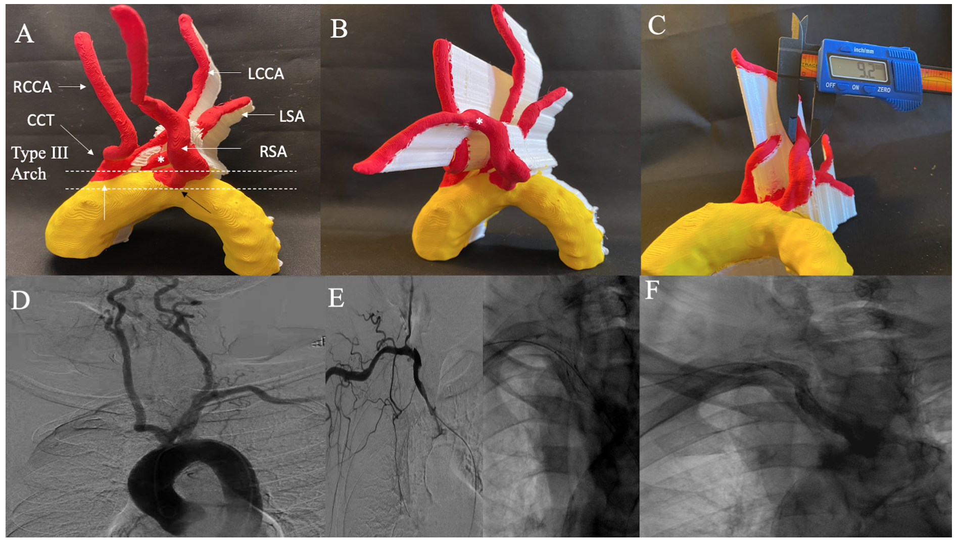
Case 1: Right retroesophageal subclavian artery in-stent restenosis. A 88-year-old female with severe in-stent restenosis (ISR) of a retroesophageal right SA stent is shown in Figure 1A. 3D-PM depicts a type III aortic arch and a variant aortic arch anatomy with a common carotid trunk which bifurcates into left and right common carotid artery (CCA), left SA originating from aortic arch, and right SA originating retroesophageal and directly from aortic arch. Severe ISR was noted at proximal edge of stent (Figure 1B). The distal reference vessel size (RVS) as measured by a digital caliper was 9.2 mm on 3D-PM and an 8- x 20-mm balloon was used for balloon angioplasty intraprocedurally (Figure 1C). Aortogram is shown from prior right SA chronic total occlusion (CTO) intervention to highlight the variant anatomy (Figure 1D). Selective right SA angiogram from index intervention and postintervention angiograms are shown for comparison in Figures 1E-1F.
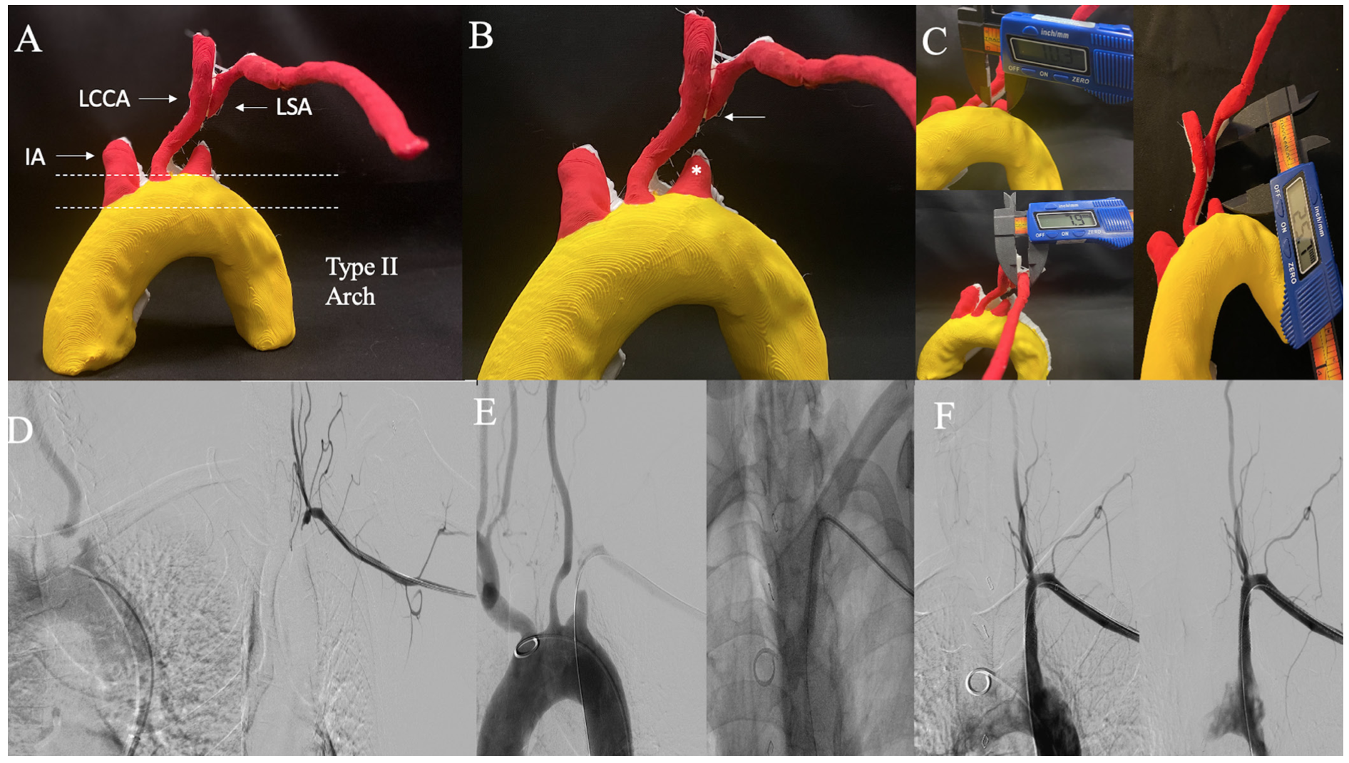
Case 2: Left subclavian artery chronic total occlusion. A 65-year-old male with left SA CTO and 3D-PM anatomy with a type II aortic arch is shown in Figure 2A. The 3D-PM accurately depicts a blunt antegrade CTO cap and tapered distal cap indicating higher procedural success rate from left brachial artery (BA) access site (Figure 2B). It is important to note that the procedure failed at first attempt at recanalization from femoral artery (FA) access and required a second attempt via left BA access which allowed successful CTO cap crossing (Figure 2E). The proximal RVS as determined on 3D-PM was 10.3 mm, distal RVS was 7.9 mm, and total lesion length (LL) was 25.7 mm as measured on 3D-PM (Figure 2C). During the procedure, an 8-x 37-mm stent was discarded because it was too long, and an 8- x 27-mm stent was subsequently deployed. Obtaining a 3D-PM preprocedurally in SA CTO can allow appropriate access site selection, route of first wire escalation, and determination of appropriate stent/balloon size selection allowing cost and procedure efficiency. Angiogram before, during, and post intervention are shown for comparison in Figures 2D-2F.
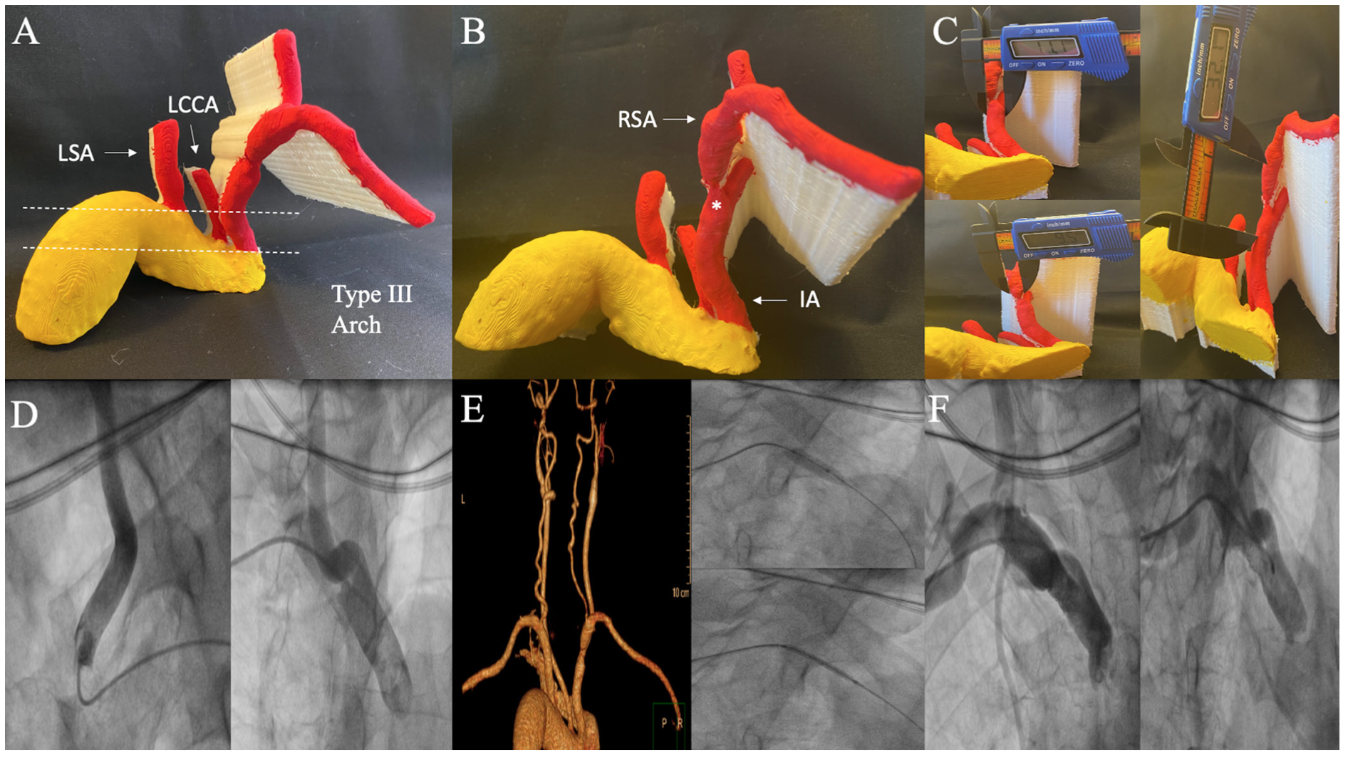
Case 3: Severe concentric right subclavian artery ostial stenosis. Critical ostial concentric right SA stenosis in a 62-year-old male is shown in Figures 3A-3B. The 3D-PM indicates a type III aortic arch. Importantly, the CTA was unable to determine if stenosis was located within distal IA or ostial SA; however, 3D-PM was able to delineate ostial SA location of the stenosis. The proximal RVS was 11.1 mm, distal RVS was 9.5 mm, and total LL was 32.1 mm (Figure 3C). Intraprocedurally, the lesion was pretreated with an 8- x 20-mm balloon and a 9- x 37-mm stent was deployed. Due to IA tortuosity and type III arch, the IA was difficult to engage via right FA access site and required a right BA access site with subsequent intervention (Figure 3D). Comparison with 3D-CTA, intraprocedural intervention via right BA access site and postintervention angiograms are shown (Figures 3E-3F). This case highlights the importance of knowledge of anatomy including aortic arch type and tortuosity so that appropriate specialized catheters and access site can be chosen preprocedurally.
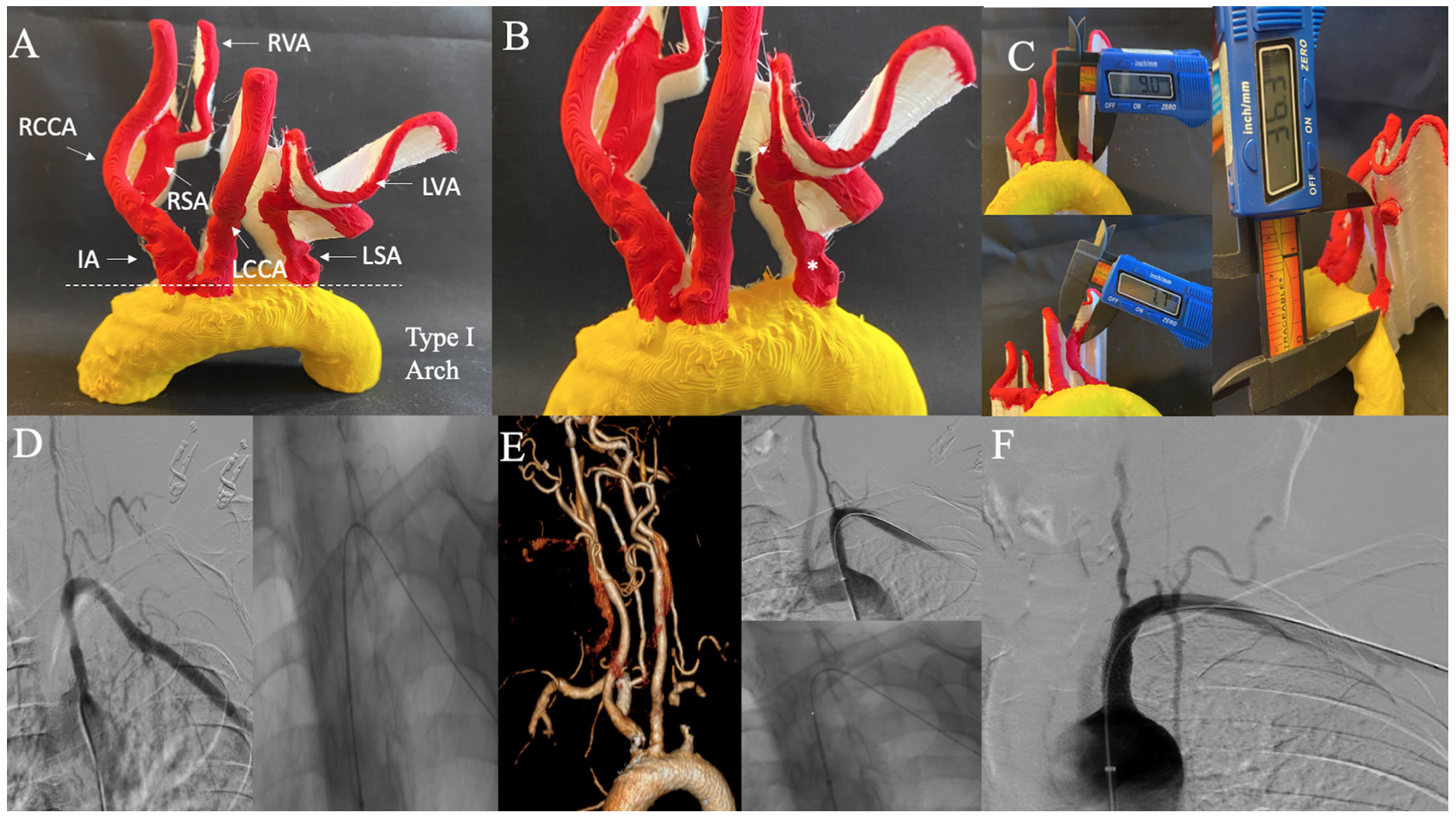
Case 4: Severe eccentric left subclavian artery stenosis. Severe eccentric left SA stenosis depicting a type I aortic arch in a 64-year-old female is shown in Figure 4A. Importantly, 3D-PM determines the lesion to end proximal to left VA (Figure 4B). Proximal RVS was 9 mm, distal RVS was 7.7 mm, and total LL was 36.3 mm (Figure 4C). Intraprocedurally, 2 overlapping stents (7 x 27 and 8 x 17 mm) were deployed as the initial stent was too short and left SA ostium uncovered atherosclerotic disease. Determination of total LL on 3D-PM and knowledge that lesion ends proximal to left VA, could have allowed appropriate stent size selection preprocedurally and thus improved procedural efficiency and cost-effectiveness. SA angiogram, intraprocedure intervention, and postprocedure angiogram along with 3D-CTA are shown for comparison (Figures 4D-4F).
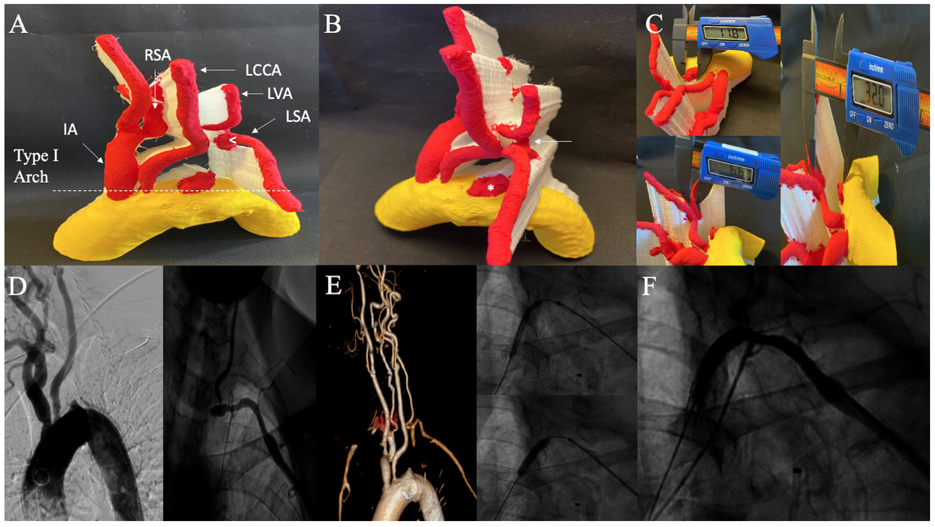
Case 5: Left subclavian artery chronic total occlusion. In a 72-year-old female with left SA CTO, 3D-PM shows labeled anatomy, type I aortic arch, and a tapered proximal cap and blunt distal cap (Figures 5A-5B). Additionally, the CTO ends proximal to the left VA which was clearly demarcated on the 3D-PM. The proximal RVS was 11.8 mm, distal RVS was 6.6 mm, and total LL was 32 mm (Figure 5C). Intraprocedurally, a 7- x 27-mm self-expanding stent was overlapped with an iCAST 6 x 16 mm covered stent. This case underscores that the availability of 3D-PM in advance of the procedure could have mitigated the need for a second overlapping stent. Aortogram, selective angiogram, intraprocedure intervention, and postintervention angiogram along with 3D-CTA are illustrated in Figures 5D-5F.
Discussion
Indication for subclavian artery endovascular interventions. A noninvasive systolic blood pressure cuff difference of >10 mm Hg has a 99% negative predictive value for diagnosis of SA stenosis, as studied in 492 patient population with left SA stenosis undergoing cardiac catheterization, and is used as a physical exam clue for further investigation.1 Common clinical indications for SA PVI include arm ischemia (57%), vertebral-subclavian steal syndrome (37%), coronary-subclavian steal syndrome (21%), and planned ipsilateral internal mammary artery for coronary artery bypass graft surgery (8%) as noted by Patel et al.5 Atherosclerosis is the most frequent pathophysiologic cause and left SA is 4 times more commonly affected than the right SA or IA.3,6 SA stenosis most commonly involves the proximal segment with the majority occurring proximal to origin of the ipsilateral VA. In cases with CTO, the pathology usually extends from ostium to origin of the VA. Endovascular treatment is typically reserved for symptomatic SA or IA stenosis. Upper extremity arm symptoms typically occur with occlusions distal to ipsilateral VA or thoracocervical/costocervical trunks, where there is a compromise of collateral flow.7 Treatment strategy of percutaneous transluminal angioplasty (PTA) alone is prone to elastic recoil and acute vessel closure. In a retrospective study of 115 patients (studied over 15-year period and data collected in 2000), patients with SA stenosis or occlusion who underwent SA PTA alone had 1-year patency rate of 76%, while it was 95% in those who also received Palmaz stents. However, long-term patency at 4 years was 59% in stented SA lesions and 68% in PTA only stenosis. This trend of worse long-term patency outcomes in stented patients is thought to be related to ISR phenomenon.8 The primary patency rates have improved with advances in stent technology. In a case series of 177 patients who underwent SA or IA stenting between 1993 and 2006, the technical success was high at 98% (90% for CTO) with a primary patency rate of 83% and secondary patency rate of 96% at a mean follow up of 3 years.5 The high CTO technical success rate was attributed to 2 access points (FA and BA) which was used in 62% of CTO cases. Rare complication of VA embolism during SA/IA interventions have been reported. This “delay of flow-reversal” phenomenon described by Ringelstein et al is related to delay in antegrade VA flow from 20 seconds to 20 minutes after SA PTA or stenting as a protective mechanism for cerebro-embolism.9 Use of VA embolic protection has been described in several case reports as a measure to prevent such phenomenon.10 VA embolism is rarely seen in SA PVI (<1% in case series) and cerebrovascular events are more often related to catheter manipulation in difficult to engage aortic arch anatomies.
Role of 3D printing in percutaneous interventions. 3D printing is an emerging technology that is currently underutilized for preprocedural planning for coronary and endovascular interventions. There has been strategic effort made toward integration of 3D printing for various cardiac interventions, including aortic and mitral valvular interventions, congenital heart interventions, and left atrial appendage occlusion interventions.11-14 Recently, progress has been made toward integration of 3D printing for preprocedural planning for coronary and endovascular interventions in various vascular beds. 3D printing of coronary artery bypass patients for preprocedural planning of complex percutaneous interventions (PCI), including CTO, can allow preprocedural determination of CTO cap morphology and distal vessel course, difficult to find occluded bypass grafts buttons, navigation of great vessel tortuosity, and engagement of difficult origin of arterial and venous grafts. This preprocedural anatomic insight translates to procedural efficiency by decreasing contrast volume, radiation dose, procedure and fluoroscopy time, and possibly success rate for CTO PCI.15 3D printing of aortic arch and carotid artery anatomy for endovascular carotid stent procedures allows preprocedural selection of catheters, navigation through great vessel tortuosity (ie, type III aortic arch), selection of balloons and stent sizes, and appreciation of distal landing zone for embolic protection device deployment.16 3D printing of renal artery anatomy for PVI allows determination of ostium angulation for optimal guide catheter manipulation and engagement, determination of RVS and LL for preprocedural selection of stent and balloon sizes, and enhanced understanding of various renal artery anatomies requiring renal vascular intervention.17 Similarly, 3D printing of mesenteric anatomy for endovascular intervention has been investigated and can be helpful in determining renal artery to celiac or superior mesenteric artery ostia distance or distance to ostia in complex anatomic subsets, such as those with prior endografts, vessel size for balloon and stent selection, intervention catheter selection, and CTO cap morphology.18
Utility of 3D printing of aortic arch and great vessel anatomy for subclavian and innominate artery interventions. Detailed knowledge and understanding of aortic arch anatomy is important for PVI, as arch anomalies have been associated with increased technical difficulty and increased risk of neurologic complications. Aortic arch and carotid anatomies associated with high endovascular carotid stent procedure failure rates or worse clinical outcomes include type II, III, and bovine arches.19-24 In the 5 cases presented herein, 3D printing of aortic arch and great vessel anatomy for SA/IA PVI is feasible, and allows augmented preprocedural planning by selection of optimal catheters and access site (Case 3: selection of BA access with type III arch and extremely tortuous IA). Additionally, complex or variant anatomy can be better appreciated preprocedurally (Case 1: retroesophageal origin of right SA directly from aortic arch). In planning of SA CTOs, 3D printing is able to clearly delineate which access site would lead to higher success rate (Case 2: left BA access site with a tapered distal cap; Case 5: FA access site with tapered proximal cap). Therefore, the wire escalation method (antegrade vs retrograde) can be chosen preprocedurally allowing improved procedural and CTO crossing efficiency. Further, RVS can be determined with precision with a digital caliper and allow for appropriate preprocedural stent and balloon selection avoiding waste of discarded stents from faulty selection of stent sizes by only visual angiographic inspection. Finally, the LL can be demarcated along with lesion location relative to VA to plan stent deployment preprocedurally (Case 4: stent deployment demonstrated to be feasible proximal to origin of ipsilateral VA).
Conclusion
3D printing of aortic arch and great vessel anatomy for SA or IA stenting can allow strategic and precision planning preprocedurally by appreciation of aortic arch type and great vessel tortuosity for catheter selection and navigation, appreciation of complex variant anatomy, CTO cap morphology for selection of access site and selection of best (antegrade vs retrograde wire escalation) method for most efficient CTO crossing success rate, balloon/stent size selection, and distance of lesion relative to ipsilateral side branches. All of these variables could potentially improve clinical outcomes with relevance to contrast volume, radiation dose, procedure, and fluoroscopy time allowing procedural and cost efficiency. The abovementioned observations require further investigation with larger, prospective, randomized trials.
Affiliations and Disclosures
From the 1Division of Cardiovascular Disease, Lankenau Medical Center, Wynnewood, Pennsylvania; 2Division of Cardiovascular and Endovascular Disease, Einstein Medical Center, Philadelphia, Pennsylvania; 3Division of Cardiovascular Research, Einstein Medical Center, Philadelphia, Pennsylvania; 4Division of Cardiovascular Disease, University of Toronto, Toronto, Ontario; and 5Division of Cardiovascular and Endovascular Disease, Pennsylvania Hospital, University of Pennsylvania Health System, Philadelphia, Pennsylvania.
Disclosure: The authors have completed and returned the ICMJE Form for Disclosure of Potential Conflicts of Interest. The authors report no conflicts of interest regarding the content herein.
Manuscript accepted September 8, 2021.
The authors report that patient consent was provided for publication of the images used herein.
Address for correspondence: Jon C. George, MD, Pennsylvania Hospital, University of Pennsylvania Health System, Philadelphia, PA 19130. Email: jcgeorgemd@gmail.com
Related Articles
- 3D Printing of Renal Arteries for Endovascular Interventions: Feasibility, Utility, and Correlation With Renal Arteriograms
- 3D Printing of Carotid Artery and Aortic Arch Anatomy: Implications for Preprocedural Planning and Carotid Stenting
- Patient Specific Coronary Artery Bypass Graft 3D-Printing: Implications for Procedural Planning in Complex Percutaneous Coronary Interventions
References
1. English JA, Carell ES, Guidera SA, Tripp HF. Angiographic prevalence and clinical predictors of left subclavian stenosis in patients undergoing diagnostic cardiac catheterization. Catheter Cardiovasc Interv. 2001;54(1):8-11. doi:10.1002/ccd.1230
2. Gutierrez GR, Mahrer P, Aharonian V, Mansukhani P, Bruss J. Prevalence of subclavian artery stenosis in patients with peripheral vascular disease. Angiology. 2001;52(3):189-194. doi:10.1177/000331970105200305
3. Potter BJ, Pinto DS. Subclavian steal syndrome. Circulation. 2014;129(22):2320-2323. doi:10.1161/CIRCULATIONAHA.113.006653
4. Krebs C, Giyanani V, Eisenberg R. Ultrasound Atlas of Vascular Disease. Appleton & Lange; 1999.
5. Patel SN, White CJ, Collins TJ, et al. Catheter-based treatment of the subclavian and innominate arteries. Catheter Cardiovasc Interv. 2008;71(7):963-968. doi:10.1002/ccd.21549
6. Schillinger M, Haumer M, Schillinger S, Mlekusch W, Ahmadi R, Minar E. Outcome of conservative versus interventional treatment of subclavian artery stenosis. J Endovasc Ther. 2002;9(2):139-146. doi:10.1177/152660280200900201
7. Casserly IP, Kapadia SR. Upper extremity intervention. In: Bhatt DL, ed. Guide to Peripheral and Cerebrovascular Intervention. Remedica; 2004.
8. Schillinger M, Haumer M, Schillinger S, Ahmadi R, Minar E. Risk stratification for subclavian artery angioplasty: is there an increased rate of restenosis after stent implantation? J Endovasc Ther. 2001;8(6):550-557. doi:10.1177/152660280100800603
9. Ringelstein EB, Zeumer H. Delayed reversal of vertebral artery blood flow following percutaneous transluminal angioplasty for subclavian steal syndrome. Neuroradiology. 1984;26(3):189-198. doi:10.1007/BF00342413
10. Rahim SA, Pitta S, Mathew V, Barsness GW, Gulati R. Subclavian artery endovascular intervention for vertebrobasilar ischemia: the use of dual arterial access and embolic protection. J Vasc Interv Radiol. 2011;22(5):730-732. doi:10.1016/j.jvir.2010.12.038
11. Maragiannis D, Jackson MS, Igo SR, et al. Replicating patient-specific severe aortic valve stenosis with functional 3D modeling. Circ Cardiovasc Imaging. 2015;8(10)e003626. doi:10.1161/CIRCIMAGING.115.003626
12. El Sabbagh A, Eleid M, Said S, et al. 3D printing for procedural simulation of transcatheter mitral valve replacement in patients with mitral annular calcification. J Am Coll Cardiol. 2017;69:1142.
13. Liu P, Liu R, Zhang Y, Liu Y, Tang X, Cheng Y. The value of 3D printing models of left atrial appendage using real-time 3D transesophageal echocardiographic data in left atrial appendage occlusion: Applications toward an era of truly personalized medicine. Cardiology. 2016;135(4):255-261. doi:10.1159/000447444
14. Chaowu Y, Hua L, Xin S. Three-dimensional printing as an aid in transcatheter closure of secundum atrial septal defect with rim deficiency: In vitro trial occlusion based on a personalized heart model. Circulation. 2016;133(17):e608-610. doi:10.1161/CIRCULATIONAHA
15. Memon S, Friend E, Samuel SP, et al. Patient specific coronary artery bypass graft 3D-printing: Implications for procedural planning in complex percutaneous coronary interventions. J Invasive Cardiol. 2021;33(8):E592-E603.
16. Memon S, Friend E, Samuel SP, et al. 3D-printing of carotid artery and aortic arch anatomy: implications for pre-procedural planning and carotid stenting. J Invasive Cardiol. 2021;33(9):E723-E729.
17. Memon S, Friend E, Kalra S, Janzer S, George JC. 3D-printing of renal arteries for endovascular interventions: Feasibility, utility and correlation with renal arteriograms. J Invasive Cardiol. 2021;33(12):E986-E992.
18. Memon S, Janzer S, Friend E, et al. 3D printing for mesenteric artery endovascular interventions: Feasibility and utility for pre-procedural planning and angiographic correlation. J Invasive Cardiol. 2022 ePub May 6.
19. Faggioli GL, Ferri M, Freyrie A et al. Aortic arch anomalies are associated with increased risk of neurological events in carotid stent procedures. Eur J Vasc Endovasc Surg. 2007;33(4):436-441. doi:10.1016/j.ejvs.2006.11.026
20. Madhwal S, Rajagopal V, Bhatt DL, Bajzer CT, Whitlow P, Kapadia SR. Predictors of difficult carotid stenting as determined by aortic arch angiography. J Invasive Cardiol. 2008;20(5):200-204.
21. Sayeed S, Stanziale SF, Wholey MH, Makaroun MS. Angiographic lesion characteristics can predict adverse outcomes after carotid artery stenting. J Vasc Surg. 2008;47(1):81-87. doi:10.1016/j.jvs.2007.09.047
22. Werner M, Bausback Y, Bräunlich S, et al. Anatomic variables contributing to a higher periprocedural incidence of stroke and TIA in carotid artery stenting: single center experience of 833 consecutive cases. Catheter Cardiovasc Interv. 2012;80(2):321-328. doi:10.1002/ccd.23483
23. Wimmer NJ, Yeh RW, Cutlip DE, Mauri L. Risk prediction for adverse events after carotid artery stenting in higher surgical risk patients. Stroke. 2012;43(12):3218-3224. doi:10.1161/STROKEAHA.112.673194
24. Ciurică S, Lopez-Sublet M, Loeys BL, et al. Arterial tortuosity. Hypertension. 2019;73(5):951-960. doi:10.1161/HYPERTENSIONAHA.118.11647


